Unity: How to create a GUI Sprite Sheet – Part 3
Posted by Dimitri | Apr 11th, 2011 | Filed under Featured, Programming

The final part of a series that explains how to create a GUI Sprite Sheet in Unity. This post will focus on explaining how the code works. For those who haven’t read the first and second parts, please do before going any further. As most post series in this website, there is a download with everything that had been explained at the end of the post.
With all images and the GUI Skin already set at the Unity Editor, now we just need some code to render the GUI on the screen. The following script correctly renders separately each element from the sprite sheet, and it’s attached to the Main Camera:
using UnityEngine;
using System.Collections;

public class GenericGUI : MonoBehaviour
{
	//the GUISkin
	public GUISkin guiSkin;

	//Draws the GUI
	void OnGUI()
	{
		//the background
		GUI.Label(new Rect(0,0,200,100),"",guiSkin.customStyles[0]);

		//the rectangular button
		//set the button position on the screen
		GUI.BeginGroup(new Rect(10,40,100,50));
		//set the button coordinates on the image
		if(GUI.Button(new Rect(0,0,128,128),"",guiSkin.customStyles[1]))
		{
			//Do something
		}
		GUI.EndGroup();

		//the round button
		//set the button position on the screen
		GUI.BeginGroup(new Rect(130,40,50,50));
		//set the button coordinates on the image
		if(GUI.Button(new Rect(0,-51,128,128),"",guiSkin.customStyles[1]))
		{
			//Do something
		}
		GUI.EndGroup();
	}
}
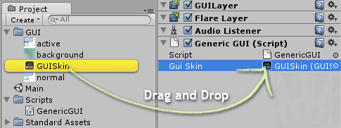
The first thing the code does is to create a public GUI Skin variable that needs to be set at the Inspector. Running the game without doing it may cause the Unity Editor to crash!

Don't forget to define this variable first!
Now, for the rest of the code, because this script renders a simple GUI, only the MonoBehaviour’s OnGUI() method needs to be called. Inside this method, the first element rendered is the background (line 13). Up to this point everything is like any other GUI script, but the next element rendered is the rectangular button, that is part of the sprite sheet.
To render this element correctly, the BeginGroup() method is called at line 17. This method defines a rectangular area on the screen to render GUI elements. Anything outside this area gets hidden. As an example, for this specific group, a square area at X:10px and Y:40px on the screen is set. This area has a width of 100px and a 50px in height. To make the sprite sheet work as expected, the position used to define the group will be the screen position where we want the GUI element to be rendered. The last two parameters (width and height) will be the width and height of the element.
By setting the GUI group values this way, we ensure that we have created a render area that has the same size of our GUI element, so basically everything that doesn’t fit inside it gets masked out.
At line 19, we draw the button, using Unity’s GUI.Button() method. Normally, this method takes a Rect that defines the position, width and height of a button. However, since its being called from inside a GUI group, the origin is now the X and Y coordinates of the group. That’s why we are going to set the GUI element position inside the sprite sheet image with the first two parameters, the other ones will be the width and height of the sprite sheet image file.
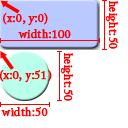
Still on the rectangular button, its top left corner inside the spritesheet is at X:0 and Y:0, and the sprite sheet image has a width and height of 128 pixels. If the X and Y values were not zero, they had to be negative, so that the image position is correctly shifted to match the area defined by the group.
That’s why this script works, it may sound a little confusing, although the code basically masks the image. After rendering the button, the GUI.Group is “closed” with the EndGroup() method (line 23). It’s extremely important to call this method.
The other button is rendered using the same logic, but with different values (line 27 through 23). Pay attention to line 29, because it’s possible to observe that it’s required to add a minus sign to the element’s coordinate inside the sprite sheet image, so it can be correctly placed inside the area defined by the group.
Case you are still wondering, this is a image that shows where these values were taken from:

Use a image editing software to figure out these values.
Final Thoughts
This sprite sheet technique is only useful when you have a lot of GUI elements. It’s not worth the trouble to join GUI elements into sprite sheets when there is up to a dozen images. If that’s not the case of your game, the advantages of using this technique is the small amount of resources allocated to render the GUI, since it’s being loaded from a small number of images. Consequently, the GUI has a smaller impact on performance. Also, the final game file gets more compact, which is good when deploying the game for mobile devices or websites.
The are quite few disadvantages too: all GUI images must be created (at least the images sizes must be previously defined) before programming the GUIs – it’s hard to change a GUI element size after sprite sheet has been created. Most importantly, both artist and programmer must understand what is necessary to make a GUI sprite sheet work, so it’s a added complexity for any game production pipeline.
Downloads
Here’s the Unity project with everything that was explained here:


Hey mate! Thanks for the tutorial.. It was a nice read, as is the rest of your blog. Keep up the good work, I’m sure it’s highly appreciated by many, despite the lack of comments.. :)
– ole
Thanks!
Hi,
Nice tutorial, one thing though. You’re hard coding all the values for the spritesheet individual sprite widths and heights in the C#. Any changes to the dimensions of the spritesheet require code changes which is pretty undesirable and could leave to nasty GUI bugs. A better approach would be to have a file that indicates all the dimensions of the images, it could be mapped via a name and read in the code and just to display the right sprites.
Even better you could then make a tool to autogenerated the sprite sheet (kinda like this: http://zwoptexapp.com/). It would create the file describing the sprite sheet for you and you don’t have to alter any code at all when the sprite sheet changes, woo!
Eddie
Yes, I know. That’s why I have already written the disadvantages of using this code at the Final Thoughts section above.
Thanks for the link to the sprite sheet tool. I’m sure it will be very useful to Mac OSX users and to people with Flash enabled browsers.